Mission

The mission of the mechanical and civil engineering department is to prepare graduate and undergraduate students to be successful professionals and leaders in global and local environments related to the workplace in industry, research, business, and management.

Mechanical Engineering

Navy Cylinder Processesing Machine


Team Leader(s)
Nicholas Gubler

Team Member(s)
Nicholas Gubler, Lucas Altamura, Richard Montanez, Brett Glock, Daniel Contaldi, Saud Alakasi

Faculty Advisor
Chiradeep Sen

Secondary Faculty Advisor
Ilya Mingareev


Navy Cylinder Processesing Machine  File Download
Project Summary
This project was requested jointly by the United States Navy and Lockheed Martin Corporation, based on a provided set of expectations for the design, to design and build a prototype Cylinder Processing Machine (CPM) that can lift and manipulate a 70lb cylinder through a series of operations, including removing it from a box, rotating it about its axis, rotating the cylinder such that the long edge is parallel to the ground, and rotate it such that the bottom of the baseplate is available for work. The final design meets these requirements by using a steel cable attached to a hydraulic cylinder that lifts a pair of steel arms attached to the grasper of the machine to lift the cylinder to a workable height. The grasper is rotated about the y-axis with a worm gearbox. The grasper utilizes a aluminum turntable that allows the machine to rotate the cylinder to rotate about the z-axis.


Project Objective
Design a machine that can grasp a 70lb cylinder by the specified attachment points, remove it from a box, and manipulate it in 5 degrees of freedom. It should accomplish this within the budget of $5,000, and should utilize no electronic or magnetic components. It should utilize no overhead lifting mechanisms, or external devices that are not mounted onto the CPM. Under no circumstances should the CPM touch the cylinder except by the specified mounting bolts, and the cylinder should not contact anything during operations. Finally, the CPM should be fully operational by a single operator.

Manufacturing Design Methods
The CPM was originally designed in Creo Parametric, where a full 3D model was created. This model was analyzed in Ansys Workbench for suitability. To physically make it, a variety of tools and methods were used, including both manual and CNC mills, manual lathe, drill press, and the bandsaw. To attach components, both manufactured steel brackets with bolts, as welding major components.

Specification
The CPM has a ground footprint of 35" x 47", and when the hydraulics are not extended, it has a height of 42.5". Once the hydraulics are extended, it has a height of 66.5". It weighs approximately 90lbs unloaded, and 160lbs when loaded with the cylinder. This means that, when loaded, each of the 12 wheels carries approximately 13.3lbs. The CPM is constructed nearly entirely out of A36 steel tubes. In order to save weight, the grasp is made of Aluminum 6061-T6.

Analysis
The CPM was analyzed in Ansys Workbench, where all critical interfaces had to have a Yield Factor of Safety of 2, and an Ultimate Factor of Safety of 4.


Acknowledgement
We extend our thanks to the United States Navy and Lockheed Martin for their support throughout this project. Special thanks goes to Anderson Crookshanks, Armstrong Ekpete, and Lauren Bowers for their guidance and contributions. We also acknowledge our faculty advisors Dr. Ilya Mingareev, Dr. Chiradeep Sen and graduate student assistants André Robidoux and Junot Damen.


Flexible End Effectors


Team Leader(s)
Belisa Villa Torres

Team Member(s)
Sastia Birju, Parker Christensen, John Fonseca, Connor Neidhart, Jennavive Nelson, Noah Reneau, Kendra Tiger, John Van Hooser, Belisa Villa Torres, Jennavive Nelson, Gabrielle Yeager

Faculty Advisor
Chiradeep Sen

Secondary Faculty Advisor
Kim Doang Nguyen


Flexible End Effectors  File Download
Project Summary
End effectors are critical components in the automotive manufacturing industry, as their performance directly impacts the cost-efficiency of operations. These specialized tools play a vital role in the assembly process by ensuring precision and reliability, essential for maintaining production standards and minimizing operational expenses. Flexible end effectors will streamline assembly lines by utilizing a single device to handle multiple marques of automobile door panels, eliminating the use of unadaptable end effectors on assembly lines. This innovation optimizes resources and lowers expenses with the innovative design focusing on gripping diverse metal door panels of cars to revolutionize assembly efficiency. The project focuses on developing a flexible end effector to enhance automotive assembly lines by having the ability to manipulate a six car door types with a single unit. The resulting system architecture was designed to offer precision and adaptability by incorporating three contact points for a secure grip and safety mechanisms to mitigate risks of power failure. Multiple design concepts were forged and rigorously assessed against durability, flexibility, and cost-effectiveness criteria. The final design consists of two main structures: the main body and the guide arms. The main body is composed of three concentric plates secured with bolts and standoff spacers. It houses the camera for part recognition and electrical components for system operation. The guide arms include L bars, a motion control assembly, and a carriage assembly. The L bars provide structural support, while the motion control assembly enables reconfiguration by using lead screws, motors, slide rails, and end housing. The carriage assembly moves along the guide arms and incorporates the gripper subassembly for a secure grip. The latch features a torsional spring-loaded latch that rotates and ensures a firm grip along different door geometries.


Project Objective
Design, build, and test a flexible end effector capable of:​ - Manipulating six different inner car door panels. - Securing each part against all six degrees of freedom. ​ - Withstanding a maximum load of 30 kg. ​ - Autonomously reconfiguring to accommodate different parts. ​ - Operating without causing visible damage to the parts.

Manufacturing Design Methods
The Flexible End Effector consists of two main structures: the main body and the cantilevered guide arms, which facilitate system reconfiguration. Together, they enable the device to recognize, reconfigure, and grasp different sheet metal parts. There are three guide arms, positioned 120 degrees apart around the central axis of the main plate. Each guide arm comprises an aluminum L bar, a motion control assembly, and a carriage assembly. The L bar carries the other two assemblies and is mounted onto the main plate. The motion control assembly moves the carriage assembly into position to grasp the sheet metal. Each includes a lead screw, motor subassembly, slide rail, and end housing. The lead screw is a long threaded rod spanning the guide arm, converting rotational motion from the motors into translational motion. This enables the carriage to move along the guide arm, reconfiguring the Flexible End Effector's shape. The motor subassembly includes the motor, motor mount, and coupler. The motor, connected to the electronics, turns the lead screw using inputted power. The coupler links the motor's output shaft to the lead screw. The slide rail, a cylindrical aluminum extrusion, guides the carriage’s path and is bolted to the underside of the L bar. The end housing, located at the cantilevered end of the guide arm, supports the lead screw and prevents the carriage from dislodging. The carriage assembly supports components that move along the guide rail to grasp the sheet metal. It includes the mounting bracket, slide, lead nut, and gripper subassembly. The mounting bracket is a metal extrusion supporting all carriage components. The slide wraps around the slide rail and is attached to the L bar. The lead nut engages with the lead screw’s threads, enabling the carriage to translate along the rail when the screw is turned. It is secured to the bracket with four bolts. The gripper subassembly includes a mounting block and a latch. The mount is a machined aluminum block housing a bearing and a torsional spring. It features a central cavity for the spring, a press-fit bearing, and a shoulder bolt passage. Two bolts secure the mount to the mounting bracket. A notch in the mount fixes one arm of the torsional spring. The latch is a machined block with a “7”-shaped notch designed to engage and secure the sheet metal’s edge. The notch functions like a wedge, pulling the part into the End Effector when pressed against an edge. The latch is bolted to the mount using a shoulder bolt that passes through the bearing and torsional spring. A second notch on the latch’s top secures the spring’s other arm. Additionally, an oil-embedded thrust bearing is sandwiched between the latch and mounting block. The gripper subassembly allows the latch to passively rotate and return to its resting position when pressed against a sheet metal edge. This rotational capability enables the Flexible End Effector to engage more locations on different sheet metal parts and ensures a


Analysis
Due to the difficulty in acquiring a functioning robotic arm typically used in automotive assembly lines, a custom testing jig was specifically designed and fabricated to support and demonstrate the capabilities of the Flexible End Effector independently. This jig served as a robust and versatile platform that allowed us to simulate a variety of operational scenarios and validate the functionality of the device without the need for full robotic integration. A comprehensive set of tests was developed and carried out using this jig. These tests included evaluations such as the Load Capacity Test, which ensured the end effector could withstand up to 30 kg without deformation, the Grasping Test, which confirmed secure gripping of various vehicle panels, and the Power Loss Holding Test, which validated grip retention in the event of power failure. Additional tests like the Planar and Rotational Motion Test, Autonomous Grasping Test, and Camera Detection Response Time Test simulated real-world conditions to ensure reliability, adaptability, and robustness. Altogether, these tests provided strong evidence that the end effector functions as intended, even in the absence of a full robotic arm system.


Acknowledgement
Advisor acknowledgement: Dr. Chiradeep Sen, and Dr. Kim-Doang Nguyen for their guidance and feedback. Graduate Student Assistant acknowledgement: Junot Damen, and Andre Robioux.


Urban Farming


Team Leader(s)
Emily Stevens

Team Member(s)
Joshua Palmer (Systems Engineer), Ben Osterlin, Ariadne Treeman-Reinke, Cody Leto, Rae Ann Dressel, Kody Butcher, Diego Salvador

Faculty Advisor
Dr. Chiradeep Sen

Secondary Faculty Advisor
Dr. Anand Balu Nellippallil


Urban Farming  File Download
Project Summary
The Urban Farming project is an entrepreneurial project tasked with examining and solving problems within urban farming technologies to make them more desirable for urban populations. Urban farming is the practice of growing plants within cities, relying on urban space, residents, and city power/water sources to grow and provide for the plants. Urban farming has many benefits for urban populations, including being a local crop source for urban populations, providing clean, green foods to those in lower socio-economic class at low costs, typically not relying on traditional harvest schedule (indoor farms can grow crops year-round), and by cleansing the air in urban areas when the plants undergo photosynthesis. However, urban farming is an underdeveloped area in terms of research and development. Currently, urban farms suffer from high costs, lack of agricultural versatility, high energy/water needs, and implementation difficulties due to lack of architectural versatility. Thus, this project aims to solve the problem of high operating costs by creating a proof-of-concept urban farming system that has lower water and electricity needs than current solutions. The proof-of-concept aims to do this by providing its own water and electricity through collection from renewable resources, creating a system that is completely self-sufficient with limited operating costs. By lowering operational costs, systems scaled upward from this proof-of-concept can be implemented in existing structures in urban areas to grow crops at low costs to provide for growing urban communities.


Project Objective
Design and construct: A. a hybrid hydroponic system to grow plants while limiting water usage and losses B. energy generation systems to capture and use environmentally collected energy to power entire hydroponic system without the use of city-provided water and electricity

Manufacturing Design Methods
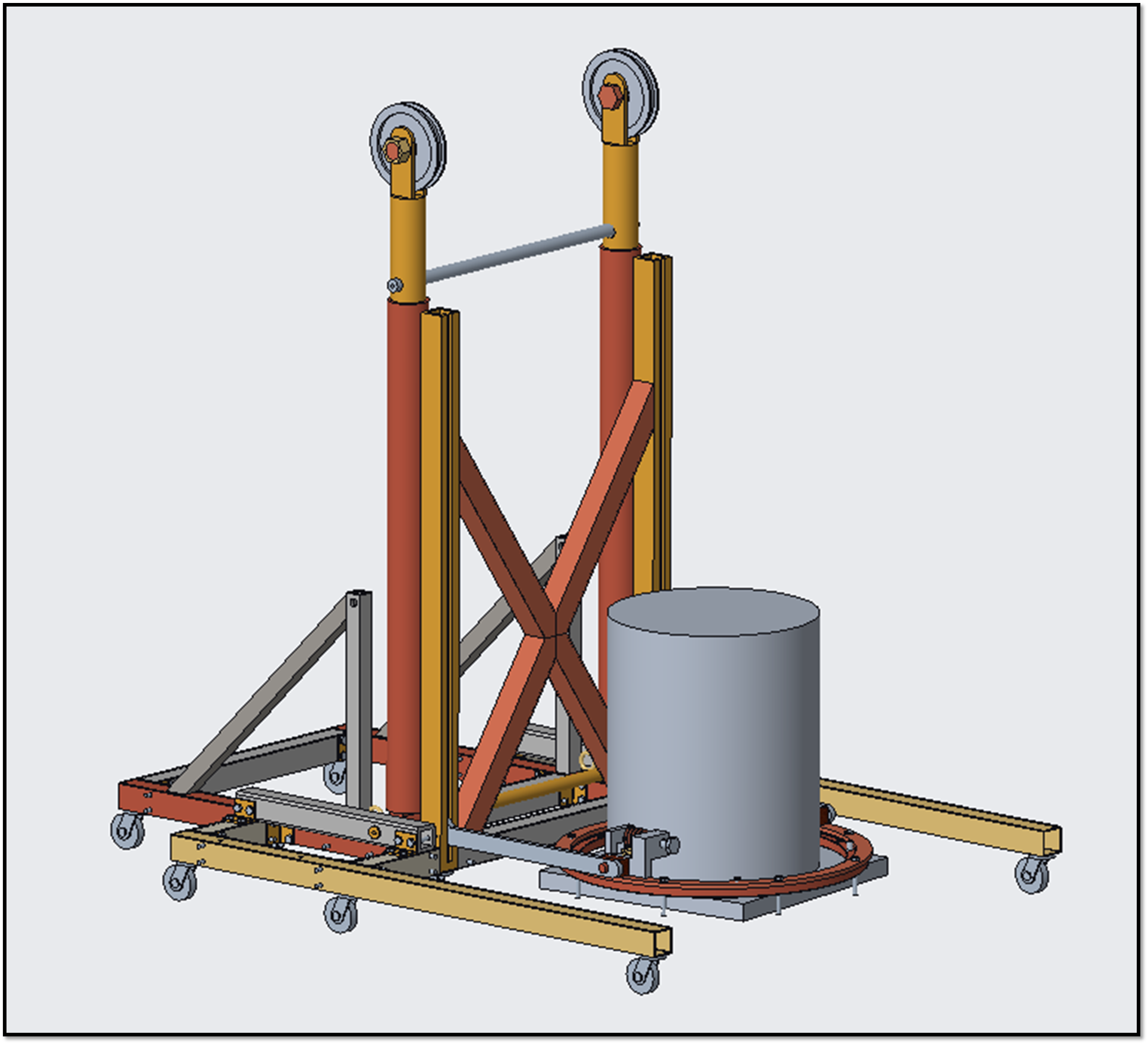
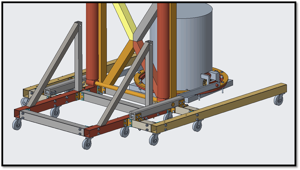
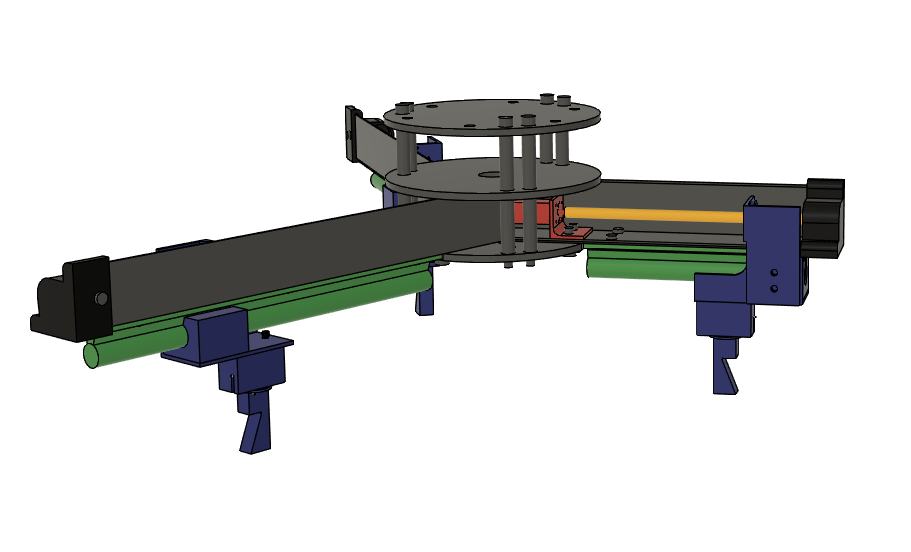
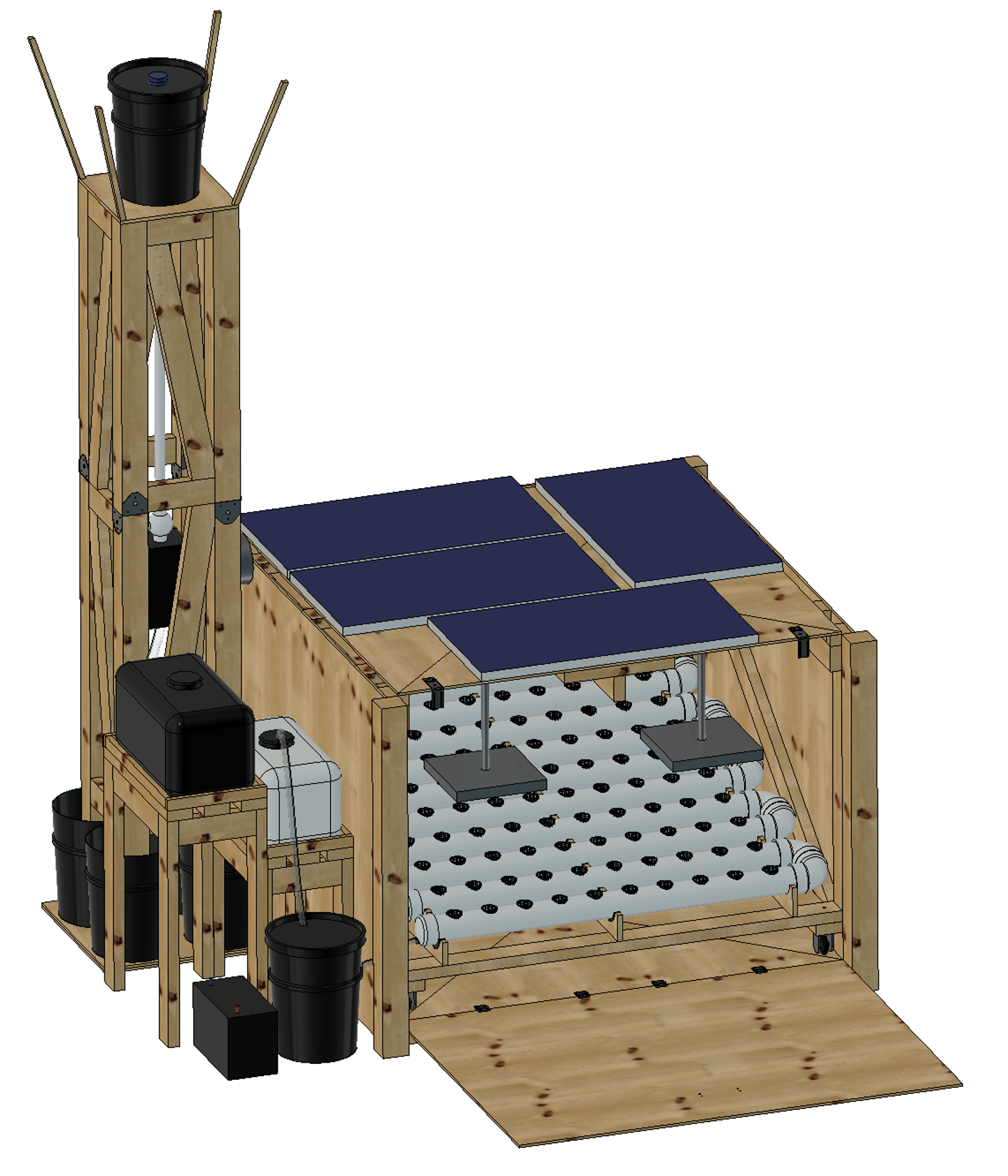
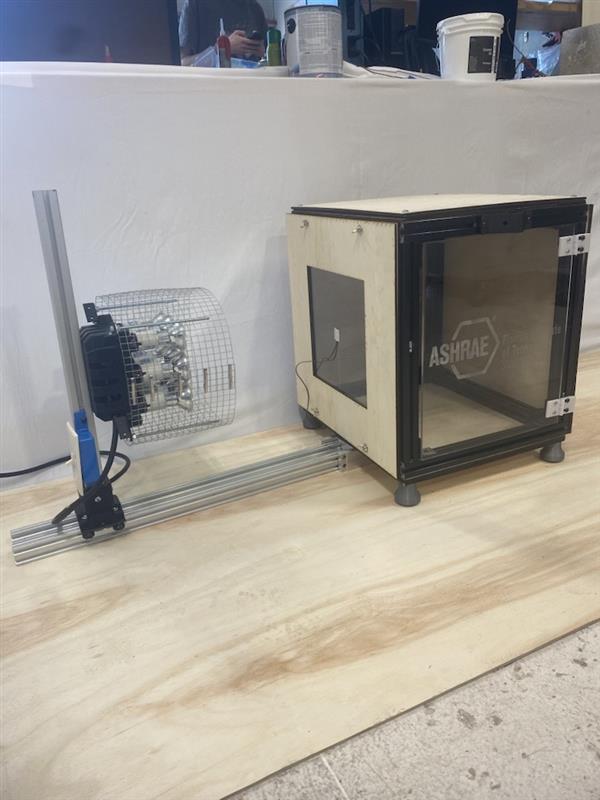
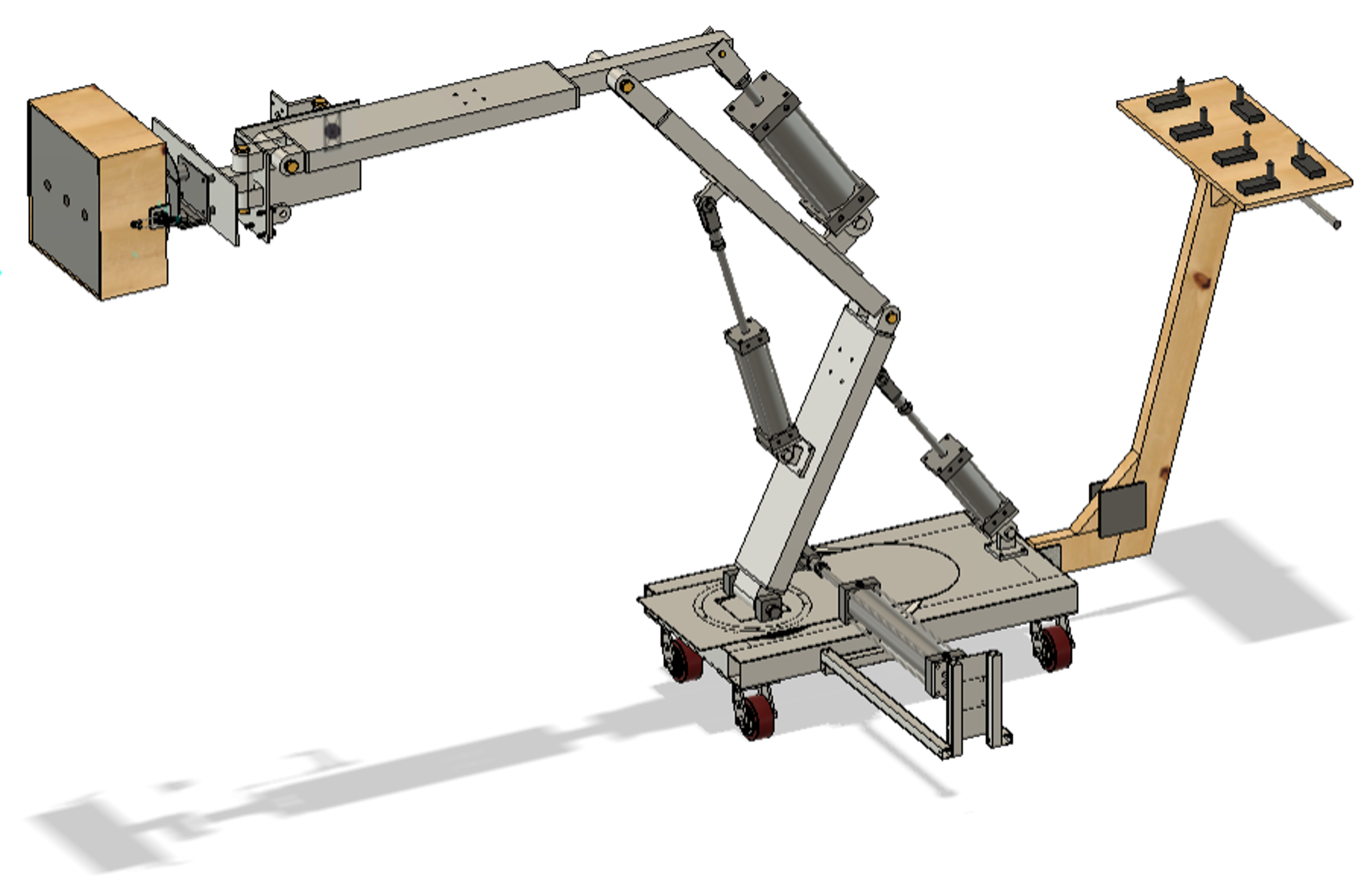
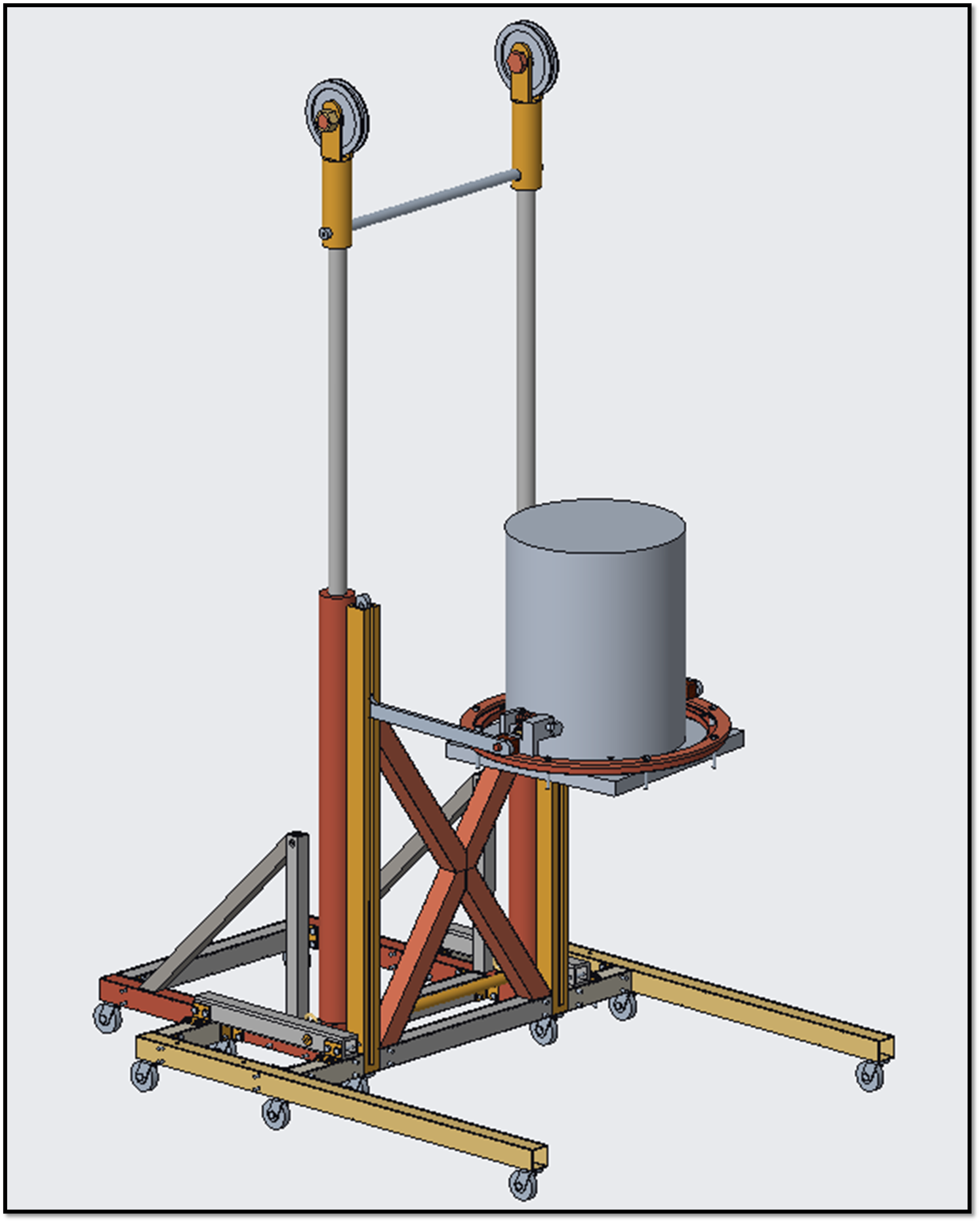
The system was designed in four independent subsystems: the isolation box, hydroponics system, storage tanks/supports subsystem, and water collection tower with two additional subsystems serving as the connections: turbine/filter/piping subsystem and power subsystem. This allowed modular design and construction for ease of transport. The isolation box consists of the warehouse-simulating structure that holds the hydroponics subsystem and components of the power subsystem. When closed, the isolation box becomes a complete box structure that isolates the hydroponics system from the outside as much as possible, but when open, the door folds downwards and serves as a table onto which the hydroponics system can be rolled for ease of planting, harvesting, and maintenance. The hydroponics system is a hybrid hydroponics system, combining components of the ebb and flow and Nutrient Film Technique (NFT) hydroponic techniques. The system relies on gravity to enable water flow, so the system forms a downward zigzag. The long pipes are not angled, while the elbows are at a 10-degree downward angle to allow water flow to the next straight pipe. Inside the end of each of the long pipes is a flow reducing baffle that requires the water from the inlet flows to reach that level before overflowing into the next section. When water leaves the system, it is pumped back into the nutrient tank for recirculation. The system rests atop laser cut plywood supports that were custom cut to hold the PVC pipe. The storage tanks/supports subsystem serves as a connection point between the water collection tower and the hydroponic system. It consists of flexible piping, a 47.5L storage tank, and a 30L nutrient tank. When needed, water from the storage tank can be moved to the nutrient tank by opening the ball valve. The water collection tower serves to collect rainwater to provide water to the hydroponic system. It is the structure that holds the turbine/filter/piping subsystem. The modular system includes two separate components. The lower part of the tower lowers the center of gravity of the tower to limit possibilities of tipping, while the upper part of the tower collects rainwater using a 26-inch x 26-inch funnel. The turbine/filter/piping subsystem consists of a 3D printed turbine, 3D printed/laser cut acrylic turbine housing, and piping. Water from the water collection tower hits the turbine, converting kinetic energy into rotational energy. The power subsystem includes all electrical components within the system. The battery serves as the center of the system. The alternator and solar panels are power inputs to the system and are DC power. The lights and pump are outputs of the system and are AC power. Thus, an inverter is connected to the battery to convert the DC power to AC power. When the turbine spins, the alternator (mated to the turbine shaft) converts the rotational energy from the turbine to electrical energy. The solar panels convert solar energy to electrical energy. The system’s power demand is 1152Wh/day, while power inputs generate an average of 1872Wh/day. Thus, the system is self-sustaining during normal operation. The battery has a storage capacity of 1280Wh, allowing the system to run for 26.67 hours without power input, providing a backup system in case the daily collected power is less than the required output power. In case of emergency, the system can be hooked up to city power if its integral subsystems are incapable of generating power.

Specification
Dimensions: Largest Dimensions: 91.35 in x 108.50 in x 119.25 in Subsystem Dimensions: Isolation Box (door open): 67.00 in x 108.50 in x 49.59 in Hydroponics System: 59.51 in x 60 in x 23.00 in Storage Tanks/Supports: 32.13 in x 60.51 in x 45.40 in Water Collection Tower: 26.00 in x 26.00 in x 119.25 in Water Specifications: Upper Water Storage Capacity: 18.93 L Storage Tank Capacity: 47.50 L Nutrient Tank Capacity: 30.00 L Hydroponic System Capacity: 8.745 L Pump Tank Capacity: 9.00 L Plant Specifications: Plant Selection: Cilantro Plant Slots: 100 Plants Per Slot: 3 Growth Time Until Maturity: 35 days Growth Time Until Harvest as Coriander: 55 days Yearly Nutrient Specifications: FloraGro: 1.538 L FloraBloom: 0.384 L FloraMicro: 0.7689 L Costs: Construction Cost: $2216.00 Operating Cost: $98.75/year

Analysis
All structural components of this project were analyzed in ANSYS Workbench to ensure that they could support typical outside forces, such as heavy rain, wind, and snow. Both the isolation box and water collection tower had a factor of safety of 15, meaning that even in the event of unnatural outdoor weather, the structures would survive with minimal danger. To determine the theoretical output for the system’s solar panels, System Advisor Model (SAM) was used. This model used Orlando’s weather data to determine average power production in various months of the year as well as a total yearly power production of 166 kWh per solar panel. To determine power output of the turbine per 5-gallon bucket fill, an excel spreadsheet was used that calculated the power output for various drop heights and turbine locations. This allowed the optimal turbine location and drop height to be determined within the project’s height limitation. Furthermore, these calculations proved that the amount of energy gained from the turbine is directly proportional to the volume of the building on which the system is mounted, while the energy gained from the solar panels is directly proportional to the surface area of the roof onto which they are mounted. Thus, larger buildings benefit more smaller buildings from this system. Lastly, energy calculations were completed to prove that with the average inputs from the solar panels and the turbine, the lights and pump can operate completely independent from the city power grid. The analysis shows that the system effectively lowers the operating cost of the system to around 98.75 dollars per year —where the only costs come from seeds and nutrients.

Future Works
Various avenues of future work are possible for this project. Firstly, to further improve the energy collection components, the design and implementation of solar tracking sensors will allow the solar panels to follow the sun. The implementation of trackers will maximize the solar energy received by the panels, increasing the amount of power production per panel. Furthermore, automation controls could be added throughout the system. Automatic drainage sensors can be added to the upper water tank when it is full, so that a human does not have to manually turn the ball valve to cause water to flow. Secondly, automatic nutrient addition systems could be added to sense the nutrient composition of the water so that nutrients can be added as needed. This would eliminate the need for daily water quality testing and allow early detection of possible plant illnesses. Further testing of the system could also be conducted with various other plant species being grown instead of just cilantro. Growing other species would prove the versatility of the system. Lastly, a large-scale system could be created in an existing building to prove that the integration of the system into an existing building would work and provide food to an urban community.


Acknowledgement
Special thanks to Graduate Student Assistants Junot Damen and André Robidoux, the faculty advisors, L3HSDC staff, and Operations Lab Managers, without whom this project could not have been completed.


ASHRAE Building Decarbonization


Team Leader(s)
Aidan Pryzgoda

Team Member(s)
Aidan Pryzgoda, Benedict Tarby, Alex French, Thomas Owenburg, and Mazin Al-Siyabi

Faculty Advisor
Dr. Hamidreza Najafi, Associate Professor of Mechanical Engineering and Director of the Innovations in Sustainable Energy and Thermal Systems (ISETS)

Secondary Faculty Advisor
Dr. Chiradeep Sen, Associate Professor of Mechanical Engineering


ASHRAE Building Decarbonization  File Download
Project Summary
Buildings account for approximately 40% of energy consumption and 36% of annual greenhouse gas emissions in the United States. Advancing energy-efficient innovations in building envelopes can substantially lower energy demand and significantly reduce the operational carbon footprint of buildings. Sponsored by the American Society of Heating, Refrigerating and Air Conditioning Engineers (ASHRAE), this project focuses on the design and development of a lab-scale apparatus to demonstrate the role of energy-efficient building envelopes in reducing energy consumption and supporting building decarbonization. The system simulates heat transfer through various wall and roof assemblies under controlled conditions, providing a hands-on tool for evaluating thermal performance and engaging students


Project Objective
Design and develop an integrated, modular laboratory equipment system for the Heat Transfer Lab to systematically study and measure parameters related to a range of building decarbonization techniques, including advanced phase change materials, and dynamic thermal testing of sustainable building materials. It would provide flexible hands-on modules for in-depth study and analysis of how these technologies impact energy efficiency and carbon reduction. The resulting equipment will become a key teaching aid that will demonstrate the principles of sustainable design, transfer of heat and help create a new generation of engineers who can exponentially impact the carbon signature of buildings of the future.

Manufacturing Design Methods
This apparatus contains Pulflex composite extrusions, lighter and more thermally insulative then aluminum extrusions. Test panels were cut via laser cutter, while the majority of parts were designed and 3-D printed custom. Some parts were machined in the Florida Tech machine shop from stock aluminum.


Future Works
This apparatus is set to become a minimum week long lab in the Florida Tech Heat Transfer Laboratory, where future students can learn about emerging building decarbonization technologies. Additionally, students will build on their knowledge of heat transfer testing and analysis.


Shell Eco-Marathon


Team Leader(s)
Pol Puigdengolas

Team Member(s)
Pol Puigdengolas, Brendan Ladwein, Nihum O'Neal, Allaith AbuHassan, Michael Panariello, Hayden Whittaker, Megan Newsom, Zije Tang, Abdulhakeem Alsamani, Jurgen Dushi

Faculty Advisor
Chiradeep Sen

Secondary Faculty Advisor
Darshan Pahinkar


Shell Eco-Marathon  File Download
Project Summary
The Shell Eco-Marathon is a competition created by Shell PLC as a challenge to create a vehicle that can achieve the maximum distance on a single gallon of gas. The current vehicle designed and built by the senior design teams of previous years is currently in an unfinished state with an unmodified motor with an undisclosed mpg, efficiency, etc. Despite this, the motorsport club has high determination to fix what was broken, upgrade whatever is needed, and have the car ready to compete in the spring. We have been requested by the Florida Tech Motorsport Club to design and build a powertrain for Florida Tech’s Shell Eco Marathon car that is more efficient than the current powertrain, while adhering to all competition regulations and staying within the allocated budget. The solution should minimize the total weight added to the vehicle and reduce the amount of fuel consumed while continuing to output a similar amount of power while maintaining structural and operational integrity.


Project Objective
Acheive a miles per gallon and powertrain output within our requirement constraints.

Manufacturing Design Methods
Manufacturing - Machine Shop, HSDC resources for tools and fasteners Design Methods - Creo, SolidWorks, Fusion 360 Design Testing (preliminary) - ANSYS workbench.

Specification
Powertrain must utilize a 4-stroke engine, electric starter, kill switch, and a clutch (any kind)


Acknowledgement
Without lasts years progress building the chassis this project would not have been possible. Thanks to Dr. Sen and Dr. Pahinkar for exceptional advising during the preliminary design process. Thanks to Andre Robidoux for helping in every step of the project as a GSA.​ Felix and The L3HSDC staff were also crucial to the completion of the project.


Waterjet Abrasive Removal System (WARS)


Team Leader(s)
Justin Sarnowski (Project Manager), Kenneth Speth (Systems Engineer)

Team Member(s)
Gabriella Cadolino, Colin Foley, Luca Garratt, Caleb Koogler, Trevor Robbins

Faculty Advisor
Dr. Anand B.Nellippallil

Secondary Faculty Advisor
Dr. Chiradeep Sen


Waterjet Abrasive Removal System (WARS)  File Download
Project Summary
The Waterjet Abrasive Removal System (WARS) is a senior design team tasked with the development and design of a product that removes settled powdered garnet abrasive from the collection tank of an OMAX GlobalMAX waterjet at the L3Harris Student Design Center (L3HSDC) to minimize both required manual effort and downtime of the waterjet. This process includes an array of submerged jets in the waterjet tank that directs a high-pressure flow of water through three nozzles to homogenize the tank mixture for transportation to a series of separation devices. The first filtration device is a cyclone separator, which uses a vortex flow to force the abrasive particles downwards while lower pressure forces the remaining fluid upwards. The second filtration device in the system is a self-cleaning filter, which contains a 50-micron stainless steel wedge wire mesh that catches the abrasive while wiper blades force the captured abrasive downward towards a disposal bucket. The water flowing through the system will settle in a surge tank, which will feed back into the submerged jets. As this is a cyclic process with the water feeding back to the waterjet tank, the system can reuse the water which minimizes the amount of water lost in the cleaning process.


Project Objective
The objective of WARS is to design, build, and demonstrate a novel engineered solution that can remove debris from a waterjet collection in a way that minimizes the manual labor required for cleaning and downtime of waterjet operation.

Manufacturing Design Methods
The final product consists of two primary subsystems classified as collections and separations. The collections subsystem agitates and transports abrasive debris into the separation subsystem. The separation subsystem then removes the abrasive and other impurities from the water and returns the filtered water back to the collection subsystem to be used as the inlet for the submerged jets array. The submerged jets is a Schedule-80 PVC piping apparatus that uses three pipe legs running down the height of the tank. These legs are connected by a crossbar pipe extending across the waterjet tank's width. Each leg extends to the bottom of the tank with a 90-degree elbow fitting. Connected to the other side of the pipe fittings is a reducer bushing with a steel pressure nozzle that pressurizes the outflow of water. All connections between pipes are bonded using PVC glue and remain fixed to the tank by attaching the system to metal bars fixed to the side legs of the jets using hose clamps. The cyclone separator consists of a stainless steel upper body cylinder section and a 3D printed ASA filament lower body cone section with an aluminum inner lining. The upper body cylinder is made of 304 stainless steel for the wall, flanges, top plate, and inlet and overflow of the cyclone, which are welded together. The top plate is bolted onto the main cylinder body with a rubber gasket to seal the system. The cone section has an epoxy coating to prevent degradation from the water. The self-cleaning filter is constructed of 304 stainless steel with two flanges welded on the top and bottom edge to allow a lid and disposal cone to be bolted on with a gasket between the surfaces. A stainless-steel shaft runs through the center axis of the filter with additional shafts running through the axis that serve as arms for the wiper blades. These blades are made of two-part polyurethane fixed to the wiper arms. The filter mesh is a stainless steel 50-micron wedge wire mesh that is housed in the filter body, sitting on the shaft support, which also serves as a filter retainer. The disposal cone at the bottom is made from 3D printed, ASA filament.

Specification
Size: 6’6” x 2’6” x 6’6” Weight (empty): 350 lbs. Estimated Weight (filled): 1000 lbs.

Analysis
The Scanning Electron Microscope located in Florida Institute of Technology’s Microscopy Lab was utilized to gain insight into the minimum significant size of particles present within a used sample of the abrasive pulled directly from the waterjet’s tank. The microscope was used to conduct an elemental analysis of both an unused and a used abrasive sample to determine that there was no large amount of non-abrasive material present in the tank. Additionally, the minimum particle size that was present within the used sample was 50 microns. The system was then designed to accommodate the minimum particle size, allowing for it to effectively remove particles up to 50 microns in size as well as up to 20 pounds of abrasive per hour.

Future Works
Future work that can be done for this project includes the development of a system that improves the current method of drying the removed abrasive. The working method used by L3HSDC staff involves placing full disposal buckets outside of the high bay for the water to evaporate out of the abrasive. This process can take several days and depends on current weather conditions at the time. An improved method for drying could have the effect of reducing the time between the collection of abrasive and final disposal as well as create a product that functions independent of weather conditions.


Acknowledgement
We would like to offer a special thanks to SAI Filters for their donation of the filter mesh, André Robidoux as our GSA, Zac Schardt, Rongxuan Ma, and the staff members of the L3HSDC, Lab Manager Tatiana Karpova and other members of the microscopy lab, and the Florida Tech Machine Shop.


Lockheed Martin - Mobile Package Handling System


Team Leader(s)
Andrew Degner (PM), Samuel Zack (SE)

Team Member(s)
Andrew Degner, Samuel Zack, Ben Schoenwiesner, Valeria Lopez, Devin Hall, Gary Lozito

Faculty Advisor
Dr. Chiradeep Sen

Secondary Faculty Advisor
Dr. Ilya Mingareev


Lockheed Martin - Mobile Package Handling System  File Download
Project Summary
Design and build a Mobile Package Handling System (MPHS) that can lift a 90 lb package from an elevated surface and place it into three different delivery zones while minimizing the amount of space, time, and manpower required. The main beneficiary of this project is Lockheed Martin Corporation. The system cannot use electronics or magnetics to perform operations. The team followed an iterative approach of research, development, and evaluation to create a design that meets all system requirements. The design was modelled in Autodesk Fusion and tested using finite element analysis in Ansys. The design uses pneumatic cylinders, controlled by toggle valves, that create a lifting force to move aluminum arm members and orient the package. The team built the design and used a testing procedure to ensure all system requirements were met.


Project Objective
Design and build a system that can lift a 90 lb package and extend the package 42" into three delivery zones. The system must be able to orient the package and extend into the delivery zones.

Manufacturing Design Methods
The team designed and built a Mobile Package Handling system to solve the problem statement and fulfill system requirements. The Florida Tech machine shop was used to cut all of the metal ordered from stock. The full system was assembled using nuts, bolts, and clevis rods in the HSDC.


Analysis
The design model was tested in Ansys using finite element analysis. A factor of safety of 2 was used to ensure all components could handle the package load. The design succeeded in all analyses.


Acknowledgement
The team would like to acknowledge the customer representatives from Lockheed Martin, Lauren Bowers and Anderson Crookshank. With their help and guidance, the team produced a system that fulfilled the system requirements. The team would also like to acknowledge our GSA, Andre Robinson, for his help throughout the project.


Civil Engineering and Construction Management

Babcock Pedestrian Bridge


Team Leader(s)
Jason Blackstone

Team Member(s)
Christina Ramirez, Jason Blackstone, Danny Richmond, Gavin Stecher, Luca Wentzel, Noah Steckley, Gabe Garrett

Faculty Advisor
Troy Nguyen


Babcock Pedestrian Bridge  File Download
Project Summary
The project aims to address the need of a safe and efficient pedestrian crossing over Babcock Street. Florida Tech’s need for this crossing is driven by the future addition of a new dormitory being constructed on the northeast corner of Babcock Street and University Boulevard. The new dormitory building will house approximately 500 students who will all require a safe and efficient method to cross the busy street. The proposed pedestrian bridge will serve as a critical link between Florida Tech’s main campus and the new dormitory, promoting safe passage while minimizing potential traffic disruptions.


Project Objective
The mission of this project is to design a pedestrian bridge that safely and efficiently spans Babcock Street, connecting Florida Tech’s main campus to a newly developed dormitory. The bridge will enhance safety and accessibility for students, faculty, and visitors. The bridge will be designed to meet all FDOT, City of Melbourne, Florida Tech, and other applicable codes and requirements. Deliverables will include construction documents detailing scheduling, cost estimation, safety measures, material specifications, and Building Information Models.


Project B.E. D.R.I.P.


Team Leader(s)
Gabriel Kuntz

Team Member(s)
Gabriel Kuntz, Lindsey Shapiro, Callie Siering, Elijah Doan, Parker Hathaway, Marguerite Fidd, Elizabeth Arrajj

Faculty Advisor
Troy Nguyen

Secondary Faculty Advisor
Nicolas Velasquez


Project B.E. D.R.I.P.  File Download
Project Summary
This is a Botanical Garden restoration project using civil engineering and construction solutions to improve the overall safety, minimize erosion, flooding, and pollution in the Botanical Garden. This project will improve the Botanical Garden so it can remain the heart of the Florida Tech campus and community.


Project Objective
Our solution offers both practical and environmental benefits that improve the landscape and ensure long-term stability. Together, the living shoreline and rain garden minimize the need for hard infrastructure and costly maintenance, while creating spaces that thrive with minimal intervention. Importantly, they also address current safety concerns by reducing unstable soil settlement, helping to prevent uneven concrete walkways and other safety concerns within the garden.  Overall, these solutions ensure the botanical garden remains safe, structurally sound, and inviting for generations of students, faculty, and visitors to enjoy as a lasting part of the campus community.

Manufacturing Design Methods
Living Shoreline Rain Garden Restoration of Walkways Pollution Prevention Measures Rebuilding Retaining Wall


Analysis
The team performed sieve analysis of the soil in the Botanical Garden to determine the roughness coefficient of the stream. Additionally, we determined the bathymetry of the stream and modeled it using HEC-RAS to determine pre and post solution velocities.

Future Works
Florida Tech will review our proposal/report and can use the information to actually carry out our vision for the Botanical Garden. In addition, future classes can use the Botanical Garden and its improvements as a living laboratory and for future senior design projects as well.


Acknowledgement
A Special Thank You to Our Sponsors! Dr. Joy Patterson & Dr. Gordon Patterson


Florida Tech Dormitory


Team Leader(s)
Jackson Sytsma

Team Member(s)
Jackson Sytsma, Logan Rutt, Chris DeAngelis, Michael LaRosa, Slater Sabel, Colin Goddard

Faculty Advisor
Troy Nguyen


Florida Tech Dormitory  File Download
Project Summary
The Florida Tech Dormitory project is a comprehensive design and construction initiative aimed at creating a modern, sustainable residence hall on the Florida Institute of Technology’s Melbourne campus. Located at Southgate Field, at the intersection of Babcock Street and University Boulevard, the proposed facility spans over 38,000 square feet and is intended to enhance the campus experience by providing updated living accommodations and amenities for students. The dormitory will include a variety of unit types, including double, triple, and quad occupancy rooms, as well as essential service spaces such as laundry rooms, mechanical and electrical rooms, and multiple stairwells to ensure accessibility and safety. The project integrates numerous amenities designed to foster a sense of community and support student well-being, including communal lounges, study areas, outdoor recreational spaces, and a grab-and-go dining option. Emphasis has been placed on sustainability throughout the design, with the inclusion of green roofs, energy-efficient mechanical systems, water conservation technologies, and environmentally responsible site planning. A centralized HVAC system, fresh air ventilation, and strategically placed air handling units on the rooftop contribute to reduced energy consumption and improved indoor air quality. Stormwater management is a significant component of the design. The site plan features two large detention ponds to handle runoff and mitigate flood risk, with innovative additions such as citronella plants in drainage inlets to help maintain water quality and deter pests. Hydrologic and hydraulic analyses guided the planning of these features to ensure effective performance under various weather conditions. In addition, the parking layout has been thoughtfully designed to optimize traffic flow, enhance pedestrian safety, and provide alternative transportation options such as bicycle racks. Lighting, security cameras, and emergency “Blue Light” stations further contribute to a safe and accessible campus environment. The estimated total cost of the project is approximately $23.75 million, covering site preparation, structural work, interior furnishings, systems installation, and general requirements. Advanced design software such as Revit and AutoCAD was used to develop detailed architectural models and site plans, ensuring accurate and efficient execution during construction. Overall, the Florida Tech Dormitory project reflects a commitment to high-quality, sustainable campus development and is poised to significantly enrich the student living experience at Florida Tech.